


Investment casting excellence doesn’t happen by chance — it’s engineered through precision, control, and continuous refinement. Porosity and cracks might seem inevitable, but with the right data, process discipline, and quality culture, they can be reduced to near zero. From material purity and shell preparation to gating design and solidification control, every stage offers an opportunity to prevent a future defect. The foundries that stand out in today’s competitive landscape are those that transform inspection data into process intelligence and corrective action.
Quality Challenges in Investment Casting: Why Defect Control Matters
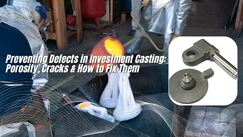
In the manufacturing of high-precision metal components with complex geometries, investment casting (also known as lost-wax casting) is widely used for its excellent dimensional accuracy and surface finish. However, in actual production, internal and surface defects such as porosity and cracks remain common and difficult to eliminate. If these defects are not promptly identified and controlled, they may lead to reduced part strength, shortened fatigue life, sealing failure, or even complete scrap.
This article systematically introduces two major types of defects commonly found in investment casting — porosity and cracks (including hot and cold cracks) — along with their formation mechanisms, detection methods, prevention strategies, and post-treatment repair techniques. The goal is to provide practical insights and references for manufacturing engineers, quality engineers, and casting technicians.
Porosity: Types, Causes, and Identification
1. Common Types and Characteristics of Porosity
In investment casting, porosity can be classified according to its causes and morphology into several categories:
| Type | Characteristics | Typical Location / Morphology | Main Driving Factors |
|---|---|---|---|
| Gas porosity | Round, smooth, nearly spherical pores | Surface pinholes, shallow pits, or internal bubbles | Gas precipitation, air entrapment, poor mold degassing |
| Hydrogen porosity | Small, dispersed internal pores | Internal micropores, often visible after machining | Excess hydrogen in melt, moisture or steam contamination |
| Shrinkage porosity | Irregular shape with sharp edges or interconnected voids | Thick sections or dead zones at the final solidification stage | Solidification shrinkage, poor feeding, cold shuts |
| Reaction / Inclusion porosity | Localized surface defects, often with oxides or inclusions | Surface or near-surface regions related to mold–metal reactions | Chemical reaction between metal and mold, inclusion entrapment, coating decomposition |
| Hot tear / Hot crack | Fine cracks caused by thermal stress during solidification | Long cracks or fissures, often at junctions of thick and thin sections | Temperature gradient, stress concentration, interrupted cooling |
How to Identify the Type of Porosity
Gas porosity typically appears round or spherical, while shrinkage porosity has irregular, angular boundaries. Porosity concentrated in thick sections or dead zones often indicates shrinkage or insufficient feeding, whereas random and dispersed pores usually point to gas release. If oxides or inclusions are present, the defect may be reaction or inclusion porosity.
2. Driving Factors Behind Porosity Formation
To effectively address porosity, it is essential to understand its root causes. The main contributing factors include:
a) Dissolved Gases and Precipitation
When metal is molten at high temperature, it can dissolve gases such as hydrogen, oxygen, and nitrogen. As the metal solidifies, gas solubility decreases, causing bubbles to form. If the melt is exposed to moisture or steam during melting or transfer, hydrogen content rises, increasing the likelihood of porosity.
b) Mold, Coating, and Core Degassing
Molds and cores containing moisture or volatile compounds release gases at high temperature, which can enter the molten metal or become trapped during filling. Poor mold venting and restricted gas escape pathways further exacerbate the problem. Excessive or improper use of coatings, fluxes, or release agents may also generate gas through decomposition.
c) Air Entrapment and Turbulence During Pouring
Excessive pouring speed or turbulence can entrap air and form bubbles. Poor gating design—such as sharp corners or sudden cross-section changes—creates dead zones and vortices, increasing the risk of gas entrapment.
d) Poor Feeding, Cooling, or Solidification Design
During cooling and solidification, metal volume decreases. Without proper feeding, shrinkage cavities form. Unbalanced temperature gradients, uneven cooling, or isolated hot spots can also cause localized shrinkage porosity or cracking. If gates or feeders freeze prematurely, they block the feeding path and result in internal voids.
In summary, porosity formation is typically the result of multiple interacting factors. Accurate identification of defect types and root causes is the foundation for implementing effective countermeasures.
Cracks (Hot / Cold Cracking): Causes, Characteristics, and Solutions
Compared with porosity, cracks are generally more destructive — they can propagate under stress, leading to fatigue failure or complete fracture. In investment casting, the most common types of cracks are hot cracks and cold cracks.
1. Hot Cracks (Hot Tears)
Causes:
- Occur during solidification when parts of the casting are still semi-solid and local stresses exceed the metal’s plastic limit.
- Often appear at junctions of thick and thin sections, sharp corners, or broken feeding paths.
- Non-uniform solidification, high temperature gradients, and constrained contraction create stress concentration leading to tearing.
Characteristics:
- Typically linear and irregular, following grain boundaries.
- Usually open at the surface and may extend partially through the section.
- Found in regions of severe thermal stress or solidification shrinkage.
Solutions:
- Optimize gating and feeding system to ensure uniform solidification and avoid isolated hot spots.
- Improve mold design to reduce restraint and allow for even shrinkage.
- Use controlled cooling rates and preheat molds to minimize thermal gradients.
- Select alloys with better hot ductility or adjust chemical composition to reduce cracking susceptibility.
2. Cold Cracks (Cold Tearing)
Causes:
- Form after solidification, often during cooling, stress relief, or post-casting operations.
- Triggered by residual stresses, rapid cooling, thermal shock, or low ductility at lower temperatures.
- Can initiate at inclusions, pores, or weak grain boundaries.
Characteristics:
- Finer, more branched cracks that may follow grain boundaries.
- Usually appear near the surface or at stress concentration points.
- Often invisible to the naked eye, requiring non-destructive testing for detection.
Solutions:
- Ensure gradual cooling and avoid rapid temperature changes during demolding or heat treatment.
- Apply proper stress-relief heat treatment to reduce internal residual stresses.
- Refine alloy composition and reduce impurities that embrittle grain boundaries.
- Enhance mold design and geometry to minimize abrupt section changes and stress concentration areas.
3. Crack Detection and Identification Methods
Cracks can be detected through visual inspection, dye penetrant testing, metallographic examination, X-ray, or CT scanning. Hot cracks are typically intergranular and visible on the surface, while cold cracks tend to be finer, near-surface, and associated with residual stress.
In summary, effective crack control requires a balance of alloy selection, mold design, process control, and stress management throughout the casting and cooling stages.
Inspection and Diagnostic Methods: How to “See” Internal Defects
For porosity and cracks, surface observation alone is usually insufficient. The following are commonly used non-destructive and destructive testing methods in the casting industry:
| Inspection Method | Applicable Range / Advantages | Limitations and Considerations |
|---|---|---|
| X-ray / CT Scanning | Capable of visualizing internal pores, cracks, and 3D defect distribution | High cost, limited penetration in thick sections, requires specialized equipment |
| Ultrasonic Testing (UT) | Detects large pores, cracks, and internal defects | Less sensitive to micro-porosity; setup is difficult for complex shapes |
| Magnetic Particle Testing (MT) | Effective for surface and near-surface cracks in ferromagnetic materials | Applicable only to ferromagnetic materials; ineffective for deep cracks |
| Dye Penetrant Testing (DPT / LPI / PT) | Low cost, simple operation, high sensitivity for surface cracks | Detects only open-to-surface cracks; requires clean, smooth surfaces |
| Metallographic Examination / Microscopy | Provides detailed observation of internal pores, cracks, and microstructure | Destructive testing method, used on sample or test pieces |
| Pressure / Leak Testing | Used for castings requiring sealing integrity; detects leakage through connected pores | Effective only for interconnected porosity; does not locate structural cracks |
| Permeability Testing / Vacuum Impregnation / Resin Sealing | Determines the presence of through-porosity or leakage channels; also useful for repair | Mainly applied during repair or quality screening for interconnected porosity |
In actual production, multiple testing methods are often combined — for example, using X-ray or CT scanning to evaluate internal structures, followed by dye penetrant testing for surface cracks. For high-value or critical components, CT scanning or metallographic sectioning is preferred for validation and in-depth analysis.
Defect Prevention Strategies: Addressing the Root Causes
The fundamental way to prevent porosity and cracking is to manage them at the source — through optimization in design, process control, materials selection, and operational discipline. The following are effective and commonly applied preventive measures.
1. Optimize Geometry and Gating System Design
- Sequential or directional solidification: Ensure metal solidifies from thin to thick sections, from edges toward the center, avoiding isolated hot spots or stagnant zones.
- Proper gating, feeding, and riser design: Ensure thick sections receive sufficient molten metal and prevent early freezing that may block feeding paths.
- Eliminate sharp corners and abrupt section changes: Reduce stress concentration, turbulence, and trapped air pockets.
- Add thermal ribs or auxiliary passages: Use extra metal channels in regions prone to cold shuts or poor feeding.
- Provide adequate venting for molds and cores: Add vents, channels, or degassing layers in areas where gas evacuation is difficult.
2. Control Material Quality and Melting Process
- Use low-gas, high-purity raw materials and avoid moisture absorption.
- Degassing and dehydrogenation treatment: Use inert gas purging (argon, nitrogen), vacuum degassing, or external refining agents to remove dissolved gases.
- Temperature control: Maintain appropriate melt temperature — too high increases gas solubility and oxidation; too low causes premature solidification and poor feeding.
- Prevent contamination, oxidation, and inclusion formation by removing slag and oxide layers promptly.
- Keep furnaces, crucibles, and pipelines dry and sealed to prevent hydrogen or moisture absorption.
3. Optimize Shell Mold and Coating Processes
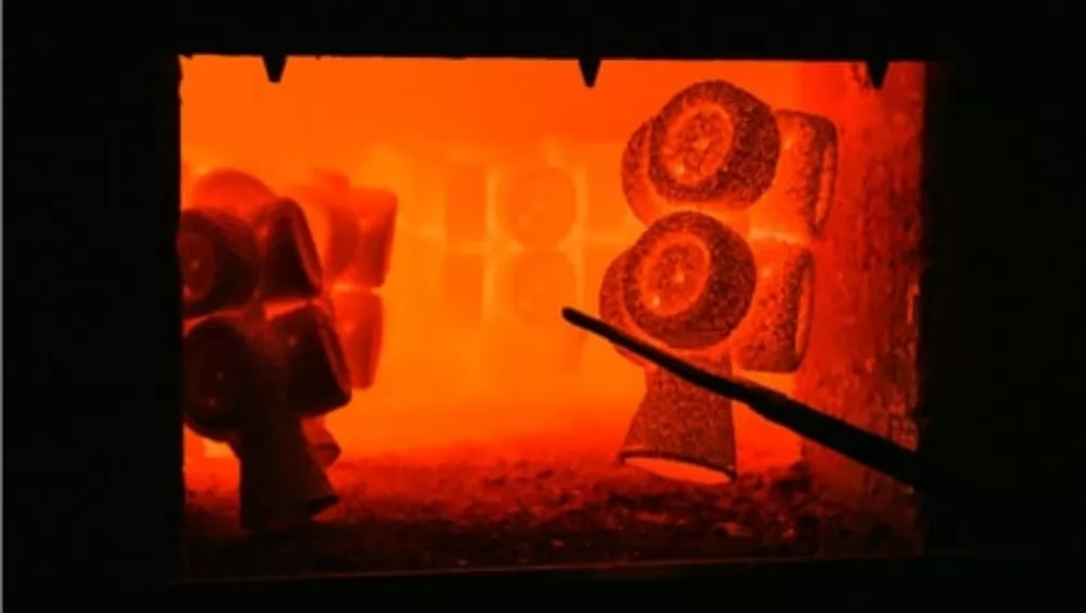
- Ensure complete drying, preheating, or burnout of shells to remove residual moisture and prevent gas generation.
- Select shell and coating materials with low volatility and minimal gas release.
- Apply coatings in controlled thickness and ensure compatibility with the process to prevent peeling or gas evolution.
- Improve dewaxing and burnout procedures to minimize residual wax or carbon content.
4. Control Pouring, Filling, and Solidification
- Control pouring speed and method: Maintain smooth metal flow to reduce turbulence and air entrapment.
- Use vacuum or inert gas protection: Apply vacuum casting or argon shielding to minimize oxidation and air inclusion.
- Apply pressure-assisted feeding: Use moderate pressure during solidification to improve feeding and densification.
- Control cooling rate and uniformity: Prevent rapid temperature drops and thermal stresses.
- Segmented or multiple pouring: For complex parts, use staged pouring or thermal isolation to balance solidification.
5. Defect Detection, Prevention, and Process Monitoring
- Use casting simulation and numerical analysis (thermal, flow, and shrinkage simulations) to predict potential defect locations.
- Continuously monitor and record key process parameters such as temperature, pressure, fill rate, and cooling curves.
- Establish process control limits and quality alert systems to detect deviations early.
- Regularly inspect and maintain equipment and tooling to prevent issues from wear, clogging, or deformation.
By applying these design and process-based preventive strategies, the occurrence of porosity and cracks can be significantly reduced, eliminating defects at their source.
Defect Repair and Remediation Strategies: What to Do When Prevention Fails
Even after process optimization, some castings may still contain minor porosity or cracks. The key is to evaluate whether these defects fall within acceptable limits, or if they can be remedied through post-processing to meet performance requirements. The following are common repair and improvement methods used in investment casting.
1. Vacuum Impregnation / Resin Sealing
This is the most common non-destructive method for sealing interconnected porosity, especially leakage-type defects. The process involves:
- Placing the casting in a vacuum chamber and evacuating trapped air from the pores.
- Introducing resin or sealant under positive pressure to fill the pores.
- Curing and cleaning to remove excess resin.
This method does not alter the casting’s geometry and has minimal impact on surface finish. It is widely used by OEMs as a standard sealing process, suitable for components where porosity affects only leak-tightness rather than structural integrity.
2. Hot Isostatic Pressing (HIP)
For load-bearing or high-density castings, hot isostatic pressing is an effective method. Under high temperature and high pressure (typically in an inert gas atmosphere), internal pores close and the material becomes more compact. HIP is commonly used for aerospace, turbine blades, and other precision structural components.
3. Welding and Metal Filling
For larger defects or cracks, the affected area can be removed and locally repaired by welding or metal filling. However, this process is complex, may introduce residual stresses, and can alter the microstructure or mechanical properties of the material. Careful evaluation and controlled welding conditions are essential.
4. Grinding, Cutting, or Recasting
Surface cracks or severe porosity can sometimes be removed by cutting or grinding, followed by local recasting or welding repair. This approach is more suitable for prototypes or limited-quantity parts rather than large-scale production.
5. Redesign or Recasting
For components with severe defects or critical structural roles, if other repair methods are ineffective or uneconomical, the optimal strategy may be to redesign the mold, gating, or feeding system and recast the part.
6. Non-Destructive Testing, Screening, and Grading
Even when all microscopic porosity cannot be eliminated, rigorous non-destructive testing and classification can help screen out defective parts. Only castings that meet required standards proceed to subsequent processing stages, ensuring product reliability.
Partner with BESSER
At BESSER, we don’t just fix defects — we help you prevent them before they ever appear. Our advanced investment casting technologies, process simulation tools, and precision quality systems are built around one promise: consistency through control. Partnering with BESSER means gaining a technical ally who understands your challenges, speaks your language, and delivers results that last — castings that are cleaner, stronger, and more reliable from the very first pour. Because in investment casting, better isn’t just a goal — it’s BESSER.